![]()
Industrial Router Crystal 3.2*2.5mm 3225 26M (26.000MHZ) 12PF 10PPM 20PPM 30PPM
![]()
0805RGB flashing
![]()
SMD aluminum electrolytic capacitor
![]()
Shenzhen excellent micro led lamp bead manufacturers 5mm colorful flash short foot self-flashing bead LED
![]()
One-piece inductor
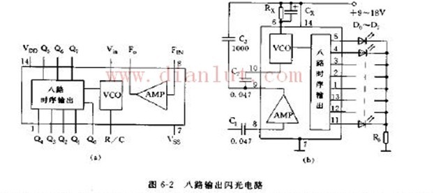
The circuit shown in Figure 6-2 is a lighting circuit that can control the speed of the eight-way timing output flash state change according to the strength of the audio signal.
Circuit principle, this circuit is assembled by using eight-way flash integrated circuit LP188. Available in a dual series in-line 14-pin plastic package. The internal logic block diagram is shown in Figure 6-2(a). The 14th and 7th pins of the circuit are the positive and negative poles of the power supply, the 6th pin R/C is the input of the voltage controlled oscillator, and the 8th and 9th pins are the audio amplifier. The input and output walls, Q11 ~ Q5 are the eight-way flash output. The circuit uses a power supply voltage of 9 to 18 V. The audio amplifier gain is 100 dB, the audio amplifier input signal is 0.5 pp, the voltage controlled oscillator input signal is 1.5 Vpp, each flash output current is greater than 20 mA, and the voltage control frequency adjustment rate is 1 to 20 times.
Figure (b) The flash point audio signal is tuned from C1 to the amplifier to amplify and control the oscillation frequency of the voltage controlled oscillator (VCO). The input signal has a large amplitude and the oscillation frequency is fast, and vice versa. The modulation rate is between 1 and 20 times, and the oscillation frequency is determined by Rx and Cx. Rx can be between 470KΩ and 1.5MΩ, and Cx is between 1 and 2μF. The current limiting resistor R0 limits the amount of operating current that is not recorded. The new flash can be assembled according to the needs, and the output terminals can also be used in parallel. If the output terminals of QOQ4, Q1Q5, Q2Q6 and Q3Q7 are connected in parallel, it can be used as a four-way fun flash circuit.
Component selection: D0 ~ D2 can choose ordinary lighting tube. R0 is between 10 and 30 Ω.


